Protocols
Subnetting
Subnetting is the organization of hosts within smaller networks using subnet masks, which allows us to route packets to their destination more efficiently. This approach is similiar to what is employed by delivery services, where the package is first routed to a sorting destination within a certain range of the final destination. By routing packets through the nearest subnet we reduce the overhead of traveling long distances and instead we make smaller hops between organized subnets.
For a single IP address there are 32 bits. This means that the IP 0.0.0.0 is equal to 00000000.00000000.00000000.00000000 in bits. This is an important concept to keep in mind, as it will help to understand subnet masks later on. When converting these to decimal IP addresses, we should keep in mind that each octet (set of 8 bits) starts at 27 and ends at 20. So, the IP 11000000.00110000.00001111.00111100 is calculated as follows, where each step is a single octet converted to decimal form.
-
11000000= 1x27 + 1x26 + 0x25 + 0x24 + 0x23 + 0x22 + 0x21 + 0x20 = 192 -
00110000= 0x27 + 0x26 + 1x25 + 1x24 + 0x23 + 0x22 + 0x21 + 0x20 = 48 -
00001111= 0x27 + 0x26 + 0x25 + 0x24 + 1x23 + 1x22 + 1x21 + 1x20 = 15 -
00111100= 0x27 + 0x26 + 1x25 + 1x24 + 1x23 + 1x22 + 0x21 + 0x20 = 60
So the IP 11000000.00110000.00001111.00111100 represented in bits is equal to 192.48.15.60, which is a class C IP address.
There are 5 classes of IP addresses, which are outlined below.
Class A - From left-to-right, everything before the first . identifies the network, and all other sections of the IP represent different devices on that network. For example, 127.56.98.102 is on the 127 network, and the device is 56.98.102. In bits, a class A IP must begin with a single 0, leaving 7 more bits available to identify the network, and the remaining 24 bits to identify devices within the network. So, with a class A IP we have 27 (128) possible network ranges, where each range has 224 (16,777,216) IPs available to assign to devices. Thus, class A IPs start at 0.0.0.0 and end at 127.255.255.255. Class A IPs are used for very large networks, notably those deployed by Internet Service Providers (ISPs). This is where your public IP adddress lives.
Class B - From left-to-right, everything before the second . identifies the network, and all other sections of the IP represent different devices on that network. For example, 128.123.58.19 is on the 128.123 network, and the device is 58.19. In bits, a class B IP must begin with 10, leaving 14 more bits available to identify the network, and the remaining 16 bits to identify devices within the network. So, with a class B IP we have 214 (16,384) possible network ranges, where each range has 216 (65,636) IPs available to assign to devices. Thus, class B IPs start at 128.0.0.0 and end at 191.255.255.255. These IPs are often used for large networks deployed by enterprises or organizations with large infrastructure. This is where a company like Google or Amazon would organize their infrastructure.
Class C - From left-to-right, everything before the third . identifies the network, and all other sections of the IP represent different devices on that network. For example, 192.48.15.60 is on the 192.48.15 network, and the device is 60. In bits, a class C IP must begin with 110, leaving 21 more bits available to identify the network, and the remaining 8 bits to identify devices within the network. So, with a class C IP we have 221 (2,097,152) possible network ranges, where each range has 28 (256) IPs available to assign to devices. Thus, class C IPs start at 192.0.0.0 and end at 223.255.255.255. These IPs are often used for small business and home networks, and is where your local IP address lives.
Class D - Class D IPs use all 32 bits for network addressing but they must begin with 1110, leaving 28 more bits available to identify the multicast IP. For example, 227.63.12.126 is just the 227.63.12.126 multicast IP address with no further identification for a host device. Thus, class D IPs start at 224.0.0.0 and end at 239.255.255.255. These addresses are used for multicasting operations and there are no host devices within this IP class. So, with a class D IP we have 228 (268,435,456) possible multicast IPs.
Class E - Class E IPs use all 32 bits for network addressing but they must begin with 1111, leaving 28 more bits available to identify the IP. So, with a class E IP we have 228 (268,435,456) possible IPs. Thus, class E IPs start at 240.0.0.0 and end at 255.255.255.255. But these addresses are not used at all and considered invalid, thus there are no host devices or networks within this IP class. The only exception is the broadcast IP address which is the same on every network - 255.255.255.255
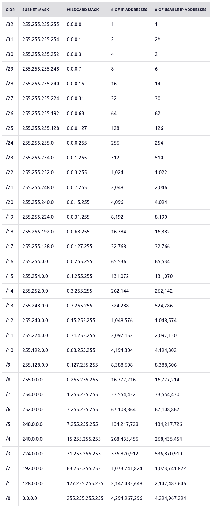
IP prefixes represent a count of bits used to identify a network, which helps to define the subnet of available hosts. For example, x.x.x.x/4 uses 4 leading bits to identify the network which can host 232 - 4 IP addresses (268,435,456)
All IP subnets possible can be seen in this table, provided at Freecodecamp - Subnet Cheatsheet
DNS
Basic Settings
To configure basic DNS for a new domain, we will only really need to create two records, after ensuring our nameservers are pointed to the correct location.
If you are just messing around with NGINX or Apache, there is no real need to purchase a domain to simply resolve your IP with DNS. Check out Freenom for a free domain name, granted it may not be your first choice - but they provide a wide range of free domains for up to 12 months.
Nameservers
A nameserver defines the path the DNS will take to resolve your domain name's IP address. If you purchased your domain already, chances are you created an account with the vendor you purchased from. Login to this account, and locate a 'DNS Records / Settings' panel to modify your DNS records using the vendors supplied control panel. If you would rather use another control panel, for example DigitalOcean, you would need to login to your domain provider's control panel and alter your domain's nameservers to reflect the below -
ns1.digitalocean.com
ns2.digitalocean.com
ns3.digitalocean.com
This allows your domain to resolve using the appropriate servers on which we have set our DNS records using their respective control panels.
DNS Records
To get started using our new domain, we will only need the below basic DNS settings -
| Type | Hostname | Value | TTL |
| A | www.website.com | 0.0.0.0 | 3600 |
| A | @.website.com | 0.0.0.0 | 3600 |
| A | *.website.com | 0.0.0.0 | 3600 |
These basic settings will allow you to further configure DNS on the host directly using a webserver if you so choose, or if you'd rather the interface using the control panel associated with your nameservers is fine as well.
DNS Record Types / Definitions
A Records
An A record maps an IPv4 address to a domain name. This determines where to direct any requests for a domain name.
AAAA Records
An AAAA record, also called a Quad A record, maps an IPv6 address to a domain name. This determines where to direct requests for a domain name in the same way that an A record does for IPv4 addresses.
CNAME Records
A CNAME record defines an alias for an A record; it points one domain to another domain instead of to an IP address. When the associated A record’s IP address changes, the CNAME will follow to the new address.
MX Records
An MX record specifies the mail servers responsible for accepting email on behalf of your domain. Providers often make multiple name servers available so that if one is offline, another can respond. Each server needs its own MX record.
NS Records
An NS record specifies the name servers, or servers that provide DNS services, for a domain or subdomain. You can use these to direct part of your traffic to another DNS service or to delegate DNS administration for a subdomain.
Web Query Path
In general, when we visit google.com for example, these are the steps that are taken to resolve the destination IP address, which is resolved from right-to-left.
- Client queries google.com via some application
- The browser checks if the DNS entry is within the local cache, then the OS checks it's local cache. If either is found to exist it returns it to the client immediately and the DNS resolution is complete; Otherwise, continue to next step
- Client query is sent to router on the LAN
- The router sends the query to the DNS Recursive Resolver if there is no entry in the cache
- The DNS Recursive Resolver routes the request the the DNS Root Nameserver (
.) - The Root server responds with the Top Level Domain (TLD) DNS server (
.com,.net,.io, etc) - The DNS Recursive Resolver routes the query to the TLD server
- The TLD server responds with the destination IP of the domain's nameserver (
shaunreed.com,google.com, etc) - The Recursive Resolver sends the request to the domain's Authoratative Nameserver
- If the request has a subdomain (like
git.shaunreed.com), the Authoratative Nameserver returns the final DNS Authoratative nameserver that is responsible for storing the subdomain's CNAME record. If there is no subdomain, this step is skipped and the destination IP is returned - The final DNS Authoratative Nameserver returns the destination IP address back to the Recursive Resolver
- The Recursive Resolver returns the resolved destination IP address to the router which initially sent the query
- The router delivers the resolved destination IP to the client IP that initially requested it on the router's LAN
- The client caches the result in the OS and web browser, assigning a Time To Live (TTL) value to indicate when the cached result should expire
Once all of these steps are completed, or a cached result is returned, the client's actual request is carried out to the destination. This is true whether the request is HTTP, HTTPS, FTP, or any other protocol within the Application layer of the TCP/IP or OSI network models.
On Ubuntu Linux systems, Mozilla stores the cache in ~/.cache/mozilla, where everything from DNS resolutions, mozilla settings, and images / thumbnails are cached.
On Ubuntu Linux systems, by default the systemd-resolved service is enabled but the /etc/systemd/resolved.conf has a default Cache value of no-negative, which means the service will not cache DNS resolutions on an OS level.
Resources and Links
TCP/IP
Transmission Control Protocol / Internet Protocol describes the standardization of packet construction and routing between software and network destinations, respectively. This means that TCP/IP allows software to be created without the overhead of determining how communication packets should be constructed for each individual piece of software. This abstraction simplifies the development process by providing a well-defined process for all software that intends to communicate between devices within the network. This simplification is also seen on the receiving end, since we know how the packets were constructed before being broken down into bits and sent over the wire, we can also reconstruct them in a similar manner on the receiving end of the transmission.
The term TCP/IP describes the connectivity between the TCP and IP protocols. The TCP protocol describes how packets should be constructed and maintains the reliable connection for the data to be sent. The IP protocol describes where to deliver the data, and handles routing to the appropriate destination. When used together, we have a reliable connection between two machines across the network.
The joining of the two individual protocols gives us TCP/IP which contains the following layers, in this order. Note that this order represents the sending device, and receiving devices will actually traverse these layers backwards while reconstructing the data to the same format in which it was originally sent.
4. Application
3. Transport
2. Internet
1. Host-to-Network
These two protocols are used together so often that the term TCP/IP is commonly used in place of referring to TCP or IP individually.
Application
Describes the application or interface that the user interacts with, such as a web browser, chat service, or email application.
This layer depends upon the subsequent layers to handle packet construction, routing, and delivery via physical infrastructure.
Protocols in this layer are HTTP, HTTPS, DNS, FTP, and Telnet
Transport
The Transport layer is responsible for providing a reliable connection between two devices on a network. With a reliable connection the data is broken down into smaller packets which can then be sent over the wire and reconstructed on the receiving end.
Upon receiving the packets, the recipient sends an ACK (acknolwedgement) of the packet having been received, and then the sender replies with an additional ACK to indicate that it is aware the packet reached it's destination.
This layer depends on subsequent layers to route the packet to the correct destination, and to provide the physical infrastructure which connects the devices within the same network.
Protocols for this layer are TCP and UDP, or Transmission Control Protocol and User Datagram Protocol.
Internet
The Internet layer is sometimes referred to as the Network layer due to it being renamed within the OSI model, which we will talk about later on this page. This layer is responsible for routing the packets to the correct destination, and handles efficiently delivering the packets by finding the shortest or least-used path available between the two devices on the network.
This layer depends on the Datalink layer to provide the physical infrastructure that allows connectivity between the two devices on the network.
The IP protocol is used in this layer, along with ARP and ICMP
Host-to-Network
The Host-to-Networ layer is sometimes referred to as the Data Link layer, Network Access layer, or the Physical layer. This layer is responsible for facillitating the physical connections and infrastructure between two devices within the same network. Examples of this
Protocols for this layer are DSL, LAN, SATNET, SONET, WiFi (802.11), and Ethernet (802.3)
Resources and Links
OSI Model
OSI
Open System Interconnection Model breaks the TCP/IP protocol down into more specific layers with more specific responsibilities.
The layers of the OSI model appear in this order when information is being sent out from the host machine. If information is being received, the layers would be traversed in reverse order from 1-7
7. Application
6. Presentation
5. Session
4. Transport
3. Network
2. Data Link
1. Physical
Application
The Application layer is the interface or software that the user interacts with in order to send communications over the network. This could be a web browsers, chat services, or email clients. This layer is where the application's protocol lives.
This layer is generally the same as the Application layer of the TCP/IP model.
Protocols in this layer are HTTP, HTTPS, DNS, SMTP, ICMP, FTP, and Telnet
Presentation
The Presentation layer is responsible for converting data into a standardized format which can optionally be encrypted or compressed before being sent across the wire. Thus, the Presentation layer is responsible for converting data into a format which can either be used by the Application layer, or passed down to the Session layer to later be sent over the wire to another device on the network.
If the application wanted to encrypt the data, this layer would do so. Similarly, if the data this layer receives is encrypted, this layer decrypts the data so the receiving Application can use it.
Session
The Session layer is responsible for establishing and maintaining a reliable connection between applications and/or devices on the network. This layer is not always used, but services such as streaming video and audio would use this layer heavily, or in the case of monitoring remote system resources or logs.
If you are familiar with sockets in programming, think of this layer as the creation of a socket between a local or remote application that may either be on the machine locally or on a remote server.
This layer is also responsible for creating checkpoints during large data transfers, which enables the download to pick up where it left off in the case of an interruption. If it were not for this layer, the download would need to be restarted from the beginning in order to ensure that all the information was sent over the wire.
Transport
The Transport layer is responsible for establishing and maintaining a reliable end-to-end connection between two devices on different networks. If the devices are on the same network, this layer is not used.
When data is being sent, this layer breaks the data down into smaller segments before sending it across the wire. When data is being received, this layer reconstructs the data into its original format.
By the sender, multiplexing is used to package local application data and send it over to the destination where demultiplexing is used in order to determine which application the message is intended for.
This layer is also responsible for error and flow control. Flow control describes the process of ensuring that the data was received using ACK signals and responses. Error control refers to the process of ensuring that the data is in the same format as it was when it was initially sent, and it has not been malformed during transmission.
Protocols for this layer are TCP and UDP, or Transmission Control Protocol and User Datagram Protocol.
Network
The Network layer is where the IP protocol lives, which as we know is responsible for routing packets to the correct destination. This layer ensures the most efficient path to the destination is used based on transmission speed and the current load. This is where packets are created.
The IP protocol is used in this layer, along with ARP and ICMP
Data Link
The Data Link layer manages how the host device interface with the network adapter. Thus, the Data Link layer manages the communication between two devices on the same network.
When data is being sent, this layer takes packets and breaks them down into frames. These frames are then sent to the physical layer for transimission.
Protocols for this layer are DSL, LAN, SATNET, SONET, WiFi (802.11)
Physical
The Physical layer is made up of the physical equipment and infrastructure which facilitates the connection between two devices. This layer transmits data only as 1's and 0's, called signals, which is then interpreted on the receiving end to reconstruct the data by following the OSI model in reverse.
The Ethernet (802.3) protocol would live on this layer, since it is a physical connection between machines
Resources and Links
TCP / UDP
TCP
Transmission Control Protocol
In TCP, the client must first contact the server and request to connect to socket which the server has been configured to listen on. The server accepts the connection and creates a new socket for communicating with the client, so there can simultaneously be several connections at once. In TCP, there is error detection and data is received in the order it is sent. This error detection comes at the cost of speed, when compared to UDP.
TCP connections are established with the following steps
- Bind socket to listen on server
- Create request from client to connect to socket
- Accept connection request and provide the server with a unique socket for communicating with this new connection
A bytestream is transmitted over a connection oriented channel and is a constant stream of data from a source to a destination. Since this happens on a connection oriented channel, bytestreams are constant and are only lost if the connection is closed.
A few protocols which use TCP connections are HTTP, HTTPS, SMTP, POP, and FTP.
TCP SSL Handshake
First, we should distinguish between a SSL session and connection.
A session can have multiple connections at any given time. SSL sessions are cached by the browser, typically until the browser is closed entirely but this may vary depending on browser and configurations. SSL sessions are also remembered by the server itself, which is also configurable on the back-end of the server but typically these sessions can last anywhere from 10 minutes to 10 hours. When a session is established, a master secret is created for the client, along with two random values - one for the client from the server, and one for the server from the client.
When a new connection is established within a valid session, new symmetric keys are established for-each connection. This is because the symmetric keys are derived from the master secret and the random values provided by both the client and server. Using these three values, symmetric keys are created for-each connection under any given session. Typically, a server will close connections after 1-2 minutes of inactivity and thus a new handshake will be required in order to establish a new connection.
Symmetric keys are only stored in RAM. This means if you shut down your device you can guarentee that a new handshake will occur the next time a HTTPS request is made to the server.
The steps required for a successful TCP SSL Handshake are seen below
- Client sends
hellomessage to the server, including a TLS version supported by the client, the cipher suites supported by the client, and a string of random bytes called theclient random - The server responds with a
hellomessage sent to the client, including the SSL certificate, the cipher suite used by the server, and a random string of bytes called theserver random - The client verifies the SSL certificate with the Certificate Autority that issued the certificate, confirming the server is who it claims to be
- The client sends one final random string of bytes called the
master secret, which is encrypted using the server's public key which was provided with the SSL certificate from the previous steps - The server decrypts the
master secretstring using it's private key - Both the server and the client produce a
session keyusing theclient random,server random, andmaster secret. Since both the client and the server produce their ownsession keyfrom the same ingredients, they both arrive at the same result and have matchingsession keys - The client sends a
finishedmessage encrypted with it's session key - The server sends a
finishedmessage encrypted with it's session key - Symmetric encryption has been established, and the handshake has completed. Secure communication can continue between the client and the server.
It is worth noting that depending on the cipher suite selected by the server in step 2, asymmetric encryption may or may not be used in the steps above. This means that steps 4-6 can vary depending on the cipher suite.
UDP
User Datagram Protocol
In UDP, there is no connection between a client and a server, packets may be sent out of order, and packets may be lost. The data keeps transmitting regardless, the sender using an IP and port which the recipient can derive from the datagram. UDP does not check for errors, and as a result has a faster speed than TCP connections. Since UDP is conectionless, there are no steps to establish a UDP connection.
UDP would be preferred in situations where data transfer does not stop if a segment is lost, like streaming a video or playing an online multiplayer game
A datagram is transmitted over a connectionless communication channel and represents just one part of a message being sent. Datagrams can be lost during transmission and resent.